Dynomotion

Group: DynoMotion Message: 11285 From: bknighton28 Date: 4/5/2015
Subject: understanding stepper motor current
I am trying to troubleshoot an axis that is supposed to run faster than I can make it. The axis, motor, drive and power supply were specified. But Instead of using the suggested gecko I am using snapamp. The 7 amp motors are set with a microStepping amplitude of 204. The supply is 21amps but there are two x axis motors. Naturally I worry that 7x4>21. The designer/vendor referred me to a gecko drive document that explains stepper current is about 2/3 of nominal. But when I look in knotion at the analog status I see each motor's ampliers sum at 7 amps or greater. Like they might be 6.9 and 0.1 but they might also be 5 and 5(approximately). This looks like 10 amps on that axis. What am I getting wrong? But when I monitor the analog status during an axis stall the supply voltage never drops below its nominal 48 volts so whatever the current the supply is keeping up.
In 2 1/2 d highest speed everything is well. It's in 3d high speed contouring that stalls are happening. The z axis is getting loud with resonance and that is when it stalls usually. The XY are rack and pinion instead of ball leadscrew like the Z. They push around a lot more mass but are having no issues. But not weight.
Group: DynoMotion Message: 11286 From: Tom Kerekes Date: 4/5/2015
Subject: Re: understanding stepper motor current
Hi Bill,

Do you have the specs on the motors?

I don't think the power supply is a problem.  It's more of a power issue than a current issue.  Because of the switching effect of the output drivers the average current from the supply will be much lower.

Do you have encoders?

Have you tried testing on the Step Response Screen with different speeds.  Also with very low acceleration so it sweeps slowly through the frequency range.  Can you identify any speed that has a resonance problem?

Regards
TK

Group: DynoMotion Message: 11287 From: bknighton28 Date: 4/5/2015
Subject: Re: understanding stepper motor current
The motors are all:
960 oz-inch
1.55v
7 amp
2 mh
.31 ohm
I have not yet put an encoder on Z but I have some differential quad encoders and a nice breakout for snapamp.
I have to have an encoder for the step/response tests correct?
Group: DynoMotion Message: 11289 From: Tom Kerekes Date: 4/6/2015
Subject: Re: understanding stepper motor current
Hi Bill,

Yes putting on an encoder would be the ideal way to tell what is happening. There is then also a possibility for applying some damping to a resonance.

Short of that you might be able to tell something by plotting the coil currents.  But that will be much harder to interpret.

Regards
TK

Group: DynoMotion Message: 11290 From: bknighton28 Date: 4/7/2015
Subject: Re: understanding stepper motor current
I have a 500 count differential output encoder connected to the troubled Z stepper axis now.
I can play with it in the step response screen but that has never helped me very much in my servo applications , instead relying on trial and error in the c program run by mach.
In the forum searches I keep seeing the idea that it is preferred to leave the Inv dist per cycle to 1 so that everything is in step cycle units. doesn't this make the V, A and J units unsuitable for using to tune the c program in mach? Next is the encoder resolution. It seems to be 2000 per revolution. When I graph a step response the command is on the wrong scale. it's a tiny bump down near 0. the much larger red encoder position sets the size of the y axis. I am not sure how I can learn anything from his until all inputs and outputs are related to each other.
Group: DynoMotion Message: 11291 From: bknighton28 Date: 4/7/2015
Subject: Re: understanding stepper motor current
Group: DynoMotion Message: 11292 From: bknighton28 Date: 4/7/2015
Subject: Re: understanding stepper motor current
if I plot axis current and position I can see it get spiked before and during a stall but I can't get a velocity. if I plot velocity it is just a bunch of square red blocks that when zoomed make up compacted waves.
Group: DynoMotion Message: 11293 From: Tom Kerekes Date: 4/7/2015
Subject: Re: understanding stepper motor current
Hi Bill,

Please post some plots and include the raw data so we can Zoom in and re-plot it ourselves.

At lower speeds and with a lower resolution encoder it is hard to measure velocity because the encoder may change very small amounts per sample (90us).  For example either 0, 1, or 2 counts so measured velocity is very quantisized is not really useful.  But if you turn off the measured velocity you should be able to see the Commanded Velocity (blue plot) clearly because that is based on floating point positions. 

Regards
TK

Group: DynoMotion Message: 11294 From: bknighton28 Date: 4/7/2015
Subject: Re: understanding stepper motor current
Attachments :
This is a test at low acceleration with the axis getting noisy.  It does not stall here.  It may not be representative because the settings are not optimum.  It is nowhere near as fast as I can get it in open loop microstepping,  Many times slower.  But maybe I can learn something about the process with this anyway.  
  @@attachment@@
Group: DynoMotion Message: 11295 From: bknighton28 Date: 4/7/2015
Subject: Re: understanding stepper motor current
since posting this I have experimented with the postion error plot and changing the I parameter. it seems an error of 0.05 or less sounds good but above that it gets noisy and is ready for a stall. using that graph it was quick to get the cl micro speeds up to what the axis will do in micro mode.
When the axis does stall, the postion gets offset and hitting zero doesn't always fix it. right as a move is executed there is a big jump with a huge error before the motion becomes smooth and the error reduced. I can't make it stop this other than by powering down the kflops and restarting.
Group: DynoMotion Message: 11296 From: Tom Kerekes Date: 4/7/2015
Subject: Re: understanding stepper motor current [1 Attachment]
Hi Bill,

I didn't realize you were running closed loop already.  You only included the data with no info on what mode, parameters, or filters were used so it makes it difficult to comment.  It would have been simpler first to run open loop and get a baseline for what the problems are.

But looking at the plots - see attached - it seems there is a bad resonance in your system at ~137Hz.

If you look at the velocity plot you can see a major oscillation in the output at point #1.  Which corresponds to when the stepping speed is ~ 73cycles/sec (point #2 & #3).

Another resonance not quite as severe occurs when the stepping speed is ~ 40cycles/sec.

I suspect moving at 40 or 73cycles per sec has a harmonic (double or quadruple frequency) that excites the 137 Hz resonance.

In the position error plot zoom-in at this time period the position error has about 13.7 oscillations over a 0.1 sec time period which indicates a frequency of 137 Hz.

The coil currents at this time period seem to be pretty nice 7 Amp sine waves.

Regards
TK


Group: DynoMotion Message: 11297 From: bknighton28 Date: 4/7/2015
Subject: Re: understanding stepper motor current [1 Attachment]
After much experimenting it will make the advertised motion in cl micro and sounds fairly smooth but when I run these settings in mach3 doing a high performance 3D contouring test it stalls about 10 percent into the program.  It seems to be a low frequency growl before the stall that I am not hearing on the step response screen.  
When setting the velocity at 137 and 73 the whole table resonates still.  

ch0->InputMode=ENCODER_MODE;
ch0->OutputMode=CL_MICROSTEP_MODE;
ch0->Vel=650;
ch0->Accel=10000;
ch0->Jerk=80000;
ch0->P=0;
ch0->I=0.0017;
ch0->D=0;
ch0->FFAccel=0;
ch0->FFVel=0.0005;
ch0->MaxI=10000;
ch0->MaxErr=1e+009;
ch0->MaxOutput=10000;
ch0->DeadBandGain=1;
ch0->DeadBandRange=0;
ch0->InputChan0=12;
ch0->InputChan1=0;
ch0->OutputChan0=8;
ch0->OutputChan1=9;
ch0->MasterAxis=-1;
ch0->LimitSwitchOptions=0x100;
ch0->LimitSwitchNegBit=0;
ch0->LimitSwitchPosBit=0;
ch0->SoftLimitPos=1e+006;
ch0->SoftLimitNeg=-1e+006;
ch0->InputGain0=0.025;
ch0->InputGain1=1;
ch0->InputOffset0=0;
ch0->InputOffset1=0;
ch0->OutputGain=1;
ch0->OutputOffset=0;
ch0->SlaveGain=1;
ch0->BacklashMode=BACKLASH_OFF;
ch0->BacklashAmount=0;
ch0->BacklashRate=0;
ch0->invDistPerCycle=1;
ch0->Lead=0;
ch0->MaxFollowingError=10000000;
ch0->StepperAmplitude=204;

ch0->iir[0].B0=1;
ch0->iir[0].B1=0;
ch0->iir[0].B2=0;
ch0->iir[0].A1=0;
ch0->iir[0].A2=0;

ch0->iir[1].B0=1;
ch0->iir[1].B1=0;
ch0->iir[1].B2=0;
ch0->iir[1].A1=0;
ch0->iir[1].A2=0;

ch0->iir[2].B0=1;
ch0->iir[2].B1=0;
ch0->iir[2].B2=0;
ch0->iir[2].A1=0;
ch0->iir[2].A2=0;


  @@attachment@@
Group: DynoMotion Message: 11298 From: Tom Kerekes Date: 4/8/2015
Subject: Re: understanding stepper motor current [2 Attachments]
Hi Bill,

You included two data sets but again forgot to explain under what conditions they were made or what you were trying to show.

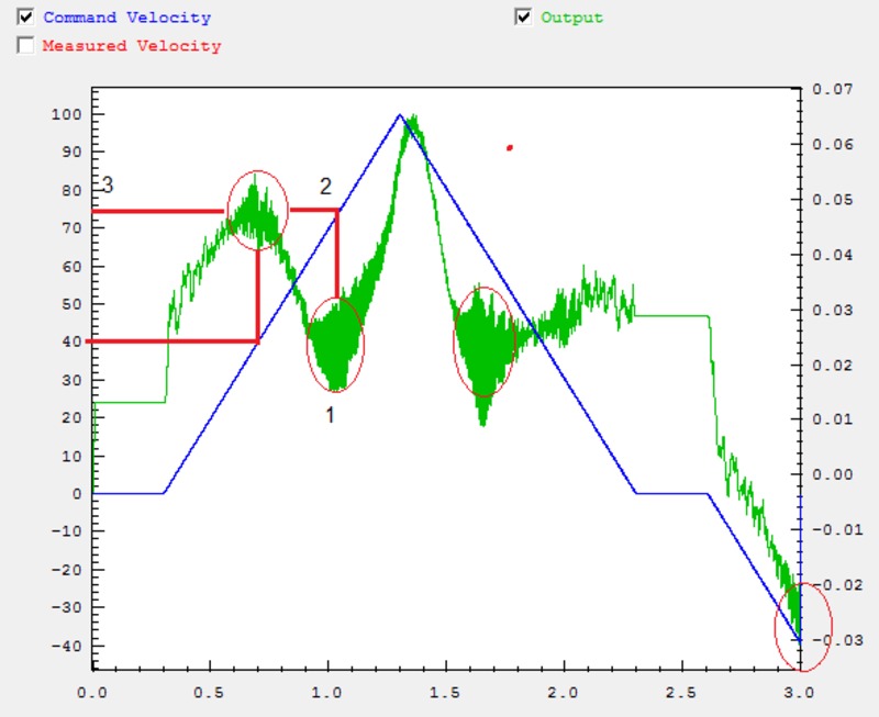
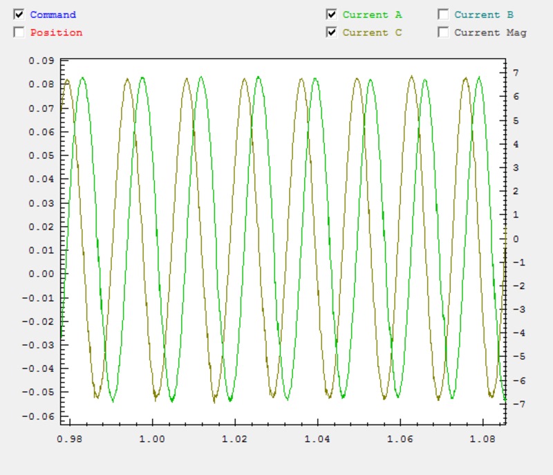
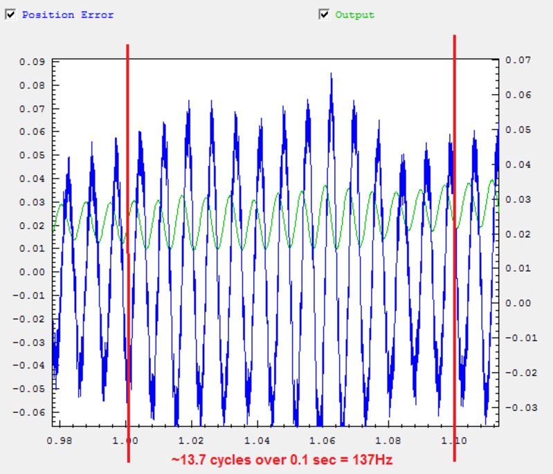
I was expecting you to show plots at 137 cycles/sec and 73 cycles/sec to show how badly the resonance is.

Mach3 is known to perform poorly on 3D contouring.  Depending on the CV settings it may violate acceleration and velocity limits.

I see two possible directions to pursue:

#1 - work at plotting. demonstrating, reducing the resonance.  See this thread on cnczone:

#2 - capture data while Mach3 is running the 3D contouring test to see exactly what is being commanded and what is happening.
Are you able to isolate a small code fragment from your GCode file that demonstrates the problem?
What version of Mach3 are you using?  What are your CV Settings?  Have you considered trying KMotionCNC?
See the example CaptureXYMotionPosDest.c are you able to run it while the problem is happening to collect data?

What is your preference or do you have other ideas?

Regards
TK


Group: DynoMotion Message: 11299 From: bknighton28 Date: 4/8/2015
Subject: Re: understanding stepper motor current [2 Attachments]
After rerunning these step response tests at 73 and 137 hz this am I think it sounds not too bad.  The motion settings are the same as my last post.  It is intended that 73, 137 and the motion settings are the conditions you need.  Is there more?  It's a nema 34 motor on a ball lead screw with a coupler made of two aluminum pieces and a rubber spider in between.   Encoder is 500 count.  
  There is also a plot of slow acceleration to 150 hz.  
It seems like a velocity error of 0.050 is a target.  Is that correct?
  I am working on the other steps in your last post one at a time and will respond.  
  @@attachment@@
Group: DynoMotion Message: 11300 From: bknighton28 Date: 4/8/2015
Subject: Re: understanding stepper motor current [2 Attachments]
Does it make sense to have a very small max following error, like 10 or less in cl micro mode so that Mach is immediately stopped? Is there a downside?  If the stepper missed that many steps can it recover back to the correct position?
Group: DynoMotion Message: 11305 From: bknighton28 Date: 4/8/2015
Subject: Re: understanding stepper motor current [2 Attachments]
It looks like option 1 because I am not as far along as I thought. Now even very simple motions like  a single rapid traverse in Mach are causing stalls. GO Z1.  I don't get it because the same velocity, acceleration and distance in step response screen is smooth.  
Group: DynoMotion Message: 11307 From: Tom Kerekes Date: 4/8/2015
Subject: Re: understanding stepper motor current
Mach3 performs only 2nd order motion (infinite Jerk).  You can simulate this in KMotion's Step Response Screen by temporarily setting the Jerk to a huge value (ie 1000X the Acceleration number).

Also are you sure you converted the Acceleration and Velocity from KFLOP units to Mach3 units correctly?

Regards
TK

Group: DynoMotion Message: 11310 From: bknighton28 Date: 4/8/2015
Subject: Re: understanding stepper motor current
for velocity I converted from kflop units to mach like this:
machV = (kflopV/50cycles) x pitch(inches) x 60 seconds/min
so 600 kflopV=141 inches/min

I did similar for acceleration so kflopA of 5000 =19.7in/sec^2

Does mach's lack of a jerk setting mean I am stuck at lower velocities then?
Group: DynoMotion Message: 11312 From: Tom Kerekes Date: 4/8/2015
Subject: Re: understanding stepper motor current
Hi Bill,

That seems correct for a leadscrew pitch of ~ 0.2 inches and assuming your Mach3 motor resolution is ~250 cycles/inchand your Mach3 units are Inches.

Regarding Jerk limitation: you should determine the difference you can achieve with and without Jerk using the Step Response Screen as described previously.  Normally max velocity should be very similar as long as low acceleration is used to achieve it.

Regards
TK

Group: DynoMotion Message: 11325 From: bknighton28 Date: 4/8/2015
Subject: Re: understanding stepper motor current
I have transitioned to kmotionCNC and 3D motion is working a lot better. I still get stalls.  But it's not during 3d motions.  It's simple down motions.  I can isolate the g-code and run it multiple times.The same motion with the same end points and speed run repeatedly will be fine most of time but sometimes it will resonate terribly and stall. Getting that speed and distance into the step response screen it it smooth and no problems.  I would post a graph if I could capture the ugliness.